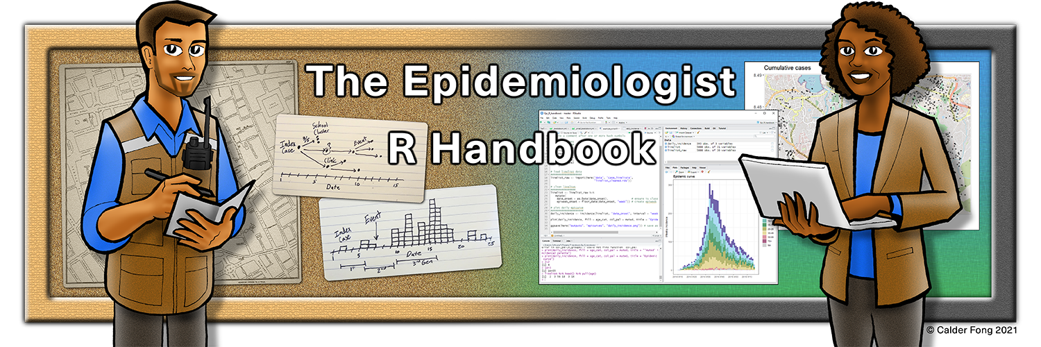
× Need help learning R? Enroll in Applied Epi's intro R course, try our free R tutorials, post in our Community Q&A forum, or ask about our R Help Desk service.

35 Diagrams and charts

This page covers code to produce:

  • Flow diagrams using DiagrammeR and the DOT language
  • Alluvial/Sankey diagrams
  • Event timelines

35.1 Preparation

Load packages

This code chunk shows the loading of packages required for the analyses. In this handbook we emphasize p_load() from pacman, which installs the package if necessary and loads it for use. You can also load installed packages with library() from base R. See the page on R basics for more information on R packages.

pacman::p_load(
  DiagrammeR,     # for flow diagrams
  networkD3,      # For alluvial/Sankey diagrams
  tidyverse)      # data management and visualization

Import data

Most of the content in this page does not require a dataset. However, in the Sankey diagram section, we will use the case linelist from a simulated Ebola epidemic. If you want to follow along for this part, click to download the “clean” linelist (as .rds file). Import data with the import() function from the rio package (it handles many file types like .xlsx, .csv, .rds - see the Import and export page for details).

# import the linelist
linelist <- import("linelist_cleaned.rds")

The first 50 rows of the linelist are displayed below.

35.2 Flow diagrams

One can use the R package DiagrammeR to create charts/flow charts. They can be static, or they can adjust somewhat dynamically based on changes in a dataset.

Tools

The function grViz() is used to create a “Graphviz” diagram. This function accepts a character string input containing instructions for making the diagram. Within that string, the instructions are written in a different language, called DOT - it is quite easy to learn the basics.

Basic structure

  1. Open the instructions grViz("
  2. Specify directionality and name of the graph, and open brackets, e.g. digraph my_flow_chart {
  3. Graph statement (layout, rank direction)
  4. Nodes statements (create nodes)
  5. Edges statements (gives links between nodes)
  6. Close the instructions }")

Simple examples

Below are two simple examples

A very minimal example:

# A minimal plot
DiagrammeR::grViz("digraph {
  
graph[layout = dot, rankdir = LR]

a
b
c

a -> b -> c
}")

An example with perhaps a bit more applied public health context:

grViz("                           # All instructions are within a large character string
digraph surveillance_diagram {    # 'digraph' means 'directional graph', then the graph name 
  
  # graph statement
  #################
  graph [layout = dot,
         rankdir = TB,
         overlap = true,
         fontsize = 10]
  
  # nodes
  #######
  node [shape = circle,           # shape = circle
       fixedsize = true
       width = 1.3]               # width of circles
  
  Primary                         # names of nodes
  Secondary
  Tertiary

  # edges
  #######
  Primary   -> Secondary [label = ' case transfer']
  Secondary -> Tertiary [label = ' case transfer']
}
")

Syntax

Basic syntax

Node names, or edge statements, can be separated with spaces, semicolons, or newlines.

Rank direction

A plot can be re-oriented to move left-to-right by adjusting the rankdir argument within the graph statement. The default is TB (top-to-bottom), but it can be LR (left-to-right), RL, or BT.

Node names

Node names can be single words, as in the simple example above. To use multi-word names or special characters (e.g. parentheses, dashes), put the node name within single quotes (’ ’). It may be easier to have a short node name, and assign a label, as shown below within brackets [ ]. If you want to have a newline within the node’s name, you must do it via a label - use \n in the node label within single quotes, as shown below.

Subgroups
Within edge statements, subgroups can be created on either side of the edge with curly brackets ({ }). The edge then applies to all nodes in the bracket - it is a shorthand.

Layouts

  • dot (set rankdir to either TB, LR, RL, BT, )
  • neato
  • twopi
  • circo

Nodes - editable attributes

  • label (text, in single quotes if multi-word)
  • fillcolor (many possible colors)
  • fontcolor
  • alpha (transparency 0-1)
  • shape (ellipse, oval, diamond, egg, plaintext, point, square, triangle)
  • style
  • sides
  • peripheries
  • fixedsize (h x w)
  • height
  • width
  • distortion
  • penwidth (width of shape border)
  • x (displacement left/right)
  • y (displacement up/down)
  • fontname
  • fontsize
  • icon

Edges - editable attributes

  • arrowsize
  • arrowhead (normal, box, crow, curve, diamond, dot, inv, none, tee, vee)
  • arrowtail
  • dir (direction, )
  • style (dashed, …)
  • color
  • alpha
  • headport (text in front of arrowhead)
  • tailport (text in behind arrowtail)
  • fontname
  • fontsize
  • fontcolor
  • penwidth (width of arrow)
  • minlen (minimum length)

Color names: hexadecimal values or ‘X11’ color names, see here for X11 details

Complex examples

The example below expands on the surveillance_diagram, adding complex node names, grouped edges, colors and styling

DiagrammeR::grViz("               # All instructions are within a large character string
digraph surveillance_diagram {    # 'digraph' means 'directional graph', then the graph name 
  
  # graph statement
  #################
  graph [layout = dot,
         rankdir = TB,            # layout top-to-bottom
         fontsize = 10]
  

  # nodes (circles)
  #################
  node [shape = circle,           # shape = circle
       fixedsize = true
       width = 1.3]                      
  
  Primary   [label = 'Primary\nFacility'] 
  Secondary [label = 'Secondary\nFacility'] 
  Tertiary  [label = 'Tertiary\nFacility'] 
  SC        [label = 'Surveillance\nCoordination',
             fontcolor = darkgreen] 
  
  # edges
  #######
  Primary   -> Secondary [label = ' case transfer',
                          fontcolor = red,
                          color = red]
  Secondary -> Tertiary [label = ' case transfer',
                          fontcolor = red,
                          color = red]
  
  # grouped edge
  {Primary Secondary Tertiary} -> SC [label = 'case reporting',
                                      fontcolor = darkgreen,
                                      color = darkgreen,
                                      style = dashed]
}
")

Sub-graph clusters

To group nodes into boxed clusters, put them within the same named subgraph (subgraph name {}). To have each subgraph identified within a bounding box, begin the name of the subgraph with “cluster”, as shown with the 4 boxes below.

DiagrammeR::grViz("             # All instructions are within a large character string
digraph surveillance_diagram {  # 'digraph' means 'directional graph', then the graph name 
  
  # graph statement
  #################
  graph [layout = dot,
         rankdir = TB,            
         overlap = true,
         fontsize = 10]
  

  # nodes (circles)
  #################
  node [shape = circle,                  # shape = circle
       fixedsize = true
       width = 1.3]                      # width of circles
  
  subgraph cluster_passive {
    Primary   [label = 'Primary\nFacility'] 
    Secondary [label = 'Secondary\nFacility'] 
    Tertiary  [label = 'Tertiary\nFacility'] 
    SC        [label = 'Surveillance\nCoordination',
               fontcolor = darkgreen] 
  }
  
  # nodes (boxes)
  ###############
  node [shape = box,                     # node shape
        fontname = Helvetica]            # text font in node
  
  subgraph cluster_active {
    Active [label = 'Active\nSurveillance'] 
    HCF_active [label = 'HCF\nActive Search']
  }
  
  subgraph cluster_EBD {
    EBS [label = 'Event-Based\nSurveillance (EBS)'] 
    'Social Media'
    Radio
  }
  
  subgraph cluster_CBS {
    CBS [label = 'Community-Based\nSurveillance (CBS)']
    RECOs
  }

  
  # edges
  #######
  {Primary Secondary Tertiary} -> SC [label = 'case reporting']

  Primary   -> Secondary [label = 'case transfer',
                          fontcolor = red]
  Secondary -> Tertiary [label = 'case transfer',
                          fontcolor = red]
  
  HCF_active -> Active
  
  {'Social Media' Radio} -> EBS
  
  RECOs -> CBS
}
")

Node shapes

The example below, borrowed from this tutorial, shows applied node shapes and a shorthand for serial edge connections

DiagrammeR::grViz("digraph {

graph [layout = dot, rankdir = LR]

# define the global styles of the nodes. We can override these in box if we wish
node [shape = rectangle, style = filled, fillcolor = Linen]

data1 [label = 'Dataset 1', shape = folder, fillcolor = Beige]
data2 [label = 'Dataset 2', shape = folder, fillcolor = Beige]
process [label =  'Process \n Data']
statistical [label = 'Statistical \n Analysis']
results [label= 'Results']

# edge definitions with the node IDs
{data1 data2}  -> process -> statistical -> results
}")

Outputs

How to handle and save outputs

  • Outputs will appear in RStudio’s Viewer pane, by default in the lower-right alongside Files, Plots, Packages, and Help.
  • To export you can “Save as image” or “Copy to clipboard” from the Viewer. The graphic will adjust to the specified size.

Parameterized figures

Here is a quote from this tutorial: https://mikeyharper.uk/flowcharts-in-r-using-diagrammer/

“Parameterized figures: A great benefit of designing figures within R is that we are able to connect the figures directly with our analysis by reading R values directly into our flowcharts. For example, suppose you have created a filtering process which removes values after each stage of a process, you can have a figure show the number of values left in the dataset after each stage of your process. To do this we, you can use the @@X symbol directly within the figure, then refer to this in the footer of the plot using [X]:, where X is the a unique numeric index.”

We encourage you to review this tutorial if parameterization is something you are interested in.

35.3 Alluvial/Sankey Diagrams

Load packages

This code chunk shows the loading of packages required for the analyses. In this handbook we emphasize p_load() from pacman, which installs the package if necessary and loads it for use. You can also load installed packages with library() from base R. See the page on R basics for more information on R packages.

We load the networkD3 package to produce the diagram, and also tidyverse for the data preparation steps.

pacman::p_load(
  networkD3,
  tidyverse)

Plotting from dataset

Plotting the connections in a dataset. Below we demonstrate using this package on the case linelist. Here is an online tutorial.

We begin by getting the case counts for each unique age category and hospital combination. We’ve removed values with missing age category for clarity. We also re-label the hospital and age_cat columns as source and target respectively. These will be the two sides of the alluvial diagram.

# counts by hospital and age category
links <- linelist %>% 
  drop_na(age_cat) %>% 
  select(hospital, age_cat) %>%
  count(hospital, age_cat) %>% 
  rename(source = hospital,
         target = age_cat)

The dataset now look like this:

Now we create a data frame of all the diagram nodes, under the column name. This consists of all the values for hospital and age_cat. Note that we ensure they are all class Character before combining them. and adjust the ID columns to be numbers instead of labels:

# The unique node names
nodes <- data.frame(
  name=c(as.character(links$source), as.character(links$target)) %>% 
    unique()
  )

nodes  # print
##                                    name
## 1                      Central Hospital
## 2                     Military Hospital
## 3                               Missing
## 4                                 Other
## 5                         Port Hospital
## 6  St. Mark's Maternity Hospital (SMMH)
## 7                                   0-4
## 8                                   5-9
## 9                                 10-14
## 10                                15-19
## 11                                20-29
## 12                                30-49
## 13                                50-69
## 14                                  70+

The we edit the links data frame, which we created above with count(). We add two numeric columns IDsource and IDtarget which will actually reflect/create the links between the nodes. These columns will hold the rownumbers (position) of the source and target nodes. 1 is subtracted so that these position numbers begin at 0 (not 1).

# match to numbers, not names
links$IDsource <- match(links$source, nodes$name)-1 
links$IDtarget <- match(links$target, nodes$name)-1

The links dataset now looks like this:

Now plot the Sankey diagram with sankeyNetwork(). You can read more about each argument by running ?sankeyNetwork in the console. Note that unless you set iterations = 0 the order of your nodes may not be as expected.

# plot
######
p <- sankeyNetwork(
  Links = links,
  Nodes = nodes,
  Source = "IDsource",
  Target = "IDtarget",
  Value = "n",
  NodeID = "name",
  units = "TWh",
  fontSize = 12,
  nodeWidth = 30,
  iterations = 0)        # ensure node order is as in data
p

Here is an example where the patient Outcome is included as well. Note in the data preparation step we have to calculate the counts of cases between age and hospital, and separately between hospital and outcome - and then bind all these counts together with bind_rows().

# counts by hospital and age category
age_hosp_links <- linelist %>% 
  drop_na(age_cat) %>% 
  select(hospital, age_cat) %>%
  count(hospital, age_cat) %>% 
  rename(source = age_cat,          # re-name
         target = hospital)

hosp_out_links <- linelist %>% 
    drop_na(age_cat) %>% 
    select(hospital, outcome) %>% 
    count(hospital, outcome) %>% 
    rename(source = hospital,       # re-name
           target = outcome)

# combine links
links <- bind_rows(age_hosp_links, hosp_out_links)

# The unique node names
nodes <- data.frame(
  name=c(as.character(links$source), as.character(links$target)) %>% 
    unique()
  )

# Create id numbers
links$IDsource <- match(links$source, nodes$name)-1 
links$IDtarget <- match(links$target, nodes$name)-1

# plot
######
p <- sankeyNetwork(Links = links,
                   Nodes = nodes,
                   Source = "IDsource",
                   Target = "IDtarget",
                   Value = "n",
                   NodeID = "name",
                   units = "TWh",
                   fontSize = 12,
                   nodeWidth = 30,
                   iterations = 0)
p

https://www.displayr.com/sankey-diagrams-r/

35.4 Event timelines

To make a timeline showing specific events, you can use the vistime package.

See this vignette

# load package
pacman::p_load(vistime,  # make the timeline
               plotly    # for interactive visualization
               )

Here is the events dataset we begin with:

p <- vistime(data)    # apply vistime

library(plotly)

# step 1: transform into a list
pp <- plotly_build(p)

# step 2: Marker size
for(i in 1:length(pp$x$data)){
  if(pp$x$data[[i]]$mode == "markers") pp$x$data[[i]]$marker$size <- 10
}

# step 3: text size
for(i in 1:length(pp$x$data)){
  if(pp$x$data[[i]]$mode == "text") pp$x$data[[i]]$textfont$size <- 10
}


# step 4: text position
for(i in 1:length(pp$x$data)){
  if(pp$x$data[[i]]$mode == "text") pp$x$data[[i]]$textposition <- "right"
}

#print
pp

35.5 DAGs

You can build a DAG manually using the DiagammeR package and DOT language as described above.

Alternatively, there are packages like ggdag and daggity

Introduction to DAGs ggdag vignette

Causal inference with dags in R

35.6 Resources

Much of the above regarding the DOT language is adapted from the tutorial at this site

Another more in-depth tutorial on DiagammeR

This page on Sankey diagrams